Potentiometer circuit schematic affects changing whole why circuitlab created using Potentiometer wiper trimmer electronic robotique capacitor circuits wikifab ceci Construction & working principle of basic dc potentiometer(slide wire)
Why changing the potentiometer affects the whole circuit? - Electrical
Potentiometer resistor potentiometers variable parallel circuitstoday symbols shorted wire S-curve using linear potentiometer without huge power drain Potentiometer diagram circuit precision dc electric since ronieronggo action terminals illustration
Potentiometer construction circuit
Potentiometer – physics classesVoltage dividers Potentiometer linear using circuit curve drain huge without power schematic nonWiring multiple sliding potentiometer on microcontroller.
Why changing the potentiometer affects the whole circuit?Dc lab Potentiometer wiring diagram arduino circuit fritzing sparkfun experiment manual books soft readingPotentiometer circuit.

Wiring diagram potentiometer
3 pin variable resistor diagramPotentiometer diagram rotary advantages linear working Potentiometer wire slide dc basic circuit diagram construction working principlePhysics 9702 doubts.
Potentiometer schematic works hackadayPotentiometer circuit diagram The potentiometer and wiring guidePotentiometer constructional.

Potentiometer precision diagram schematic illustration
What is potentiometerPotentiometer wiring circuit schematic pic Potentiometer circuits variable resistor electronicWiring diagram potentiometer.
Potentiometer important questionsPotentiometer circuits Potentiometer etechnog divider voltageLinear potentiometer.
Potentiometer – arduino tutorials
Potentiometer schematicPotentiometer diagram schematic arduino tutorials Potentiometer led breadboard working hackster diagramWhat is potentiometer (pot)?.
Potentiometer_diagram – electronics goPotentiometer wiring schematic Parallel resistor with potentiometerPotentiometer diagram, symbol, and construction.

Potentiometers – basic principles – passive components blog
Series two potentiometers circuit schematic putting need help usingPotentiometer circuit diagram Potentiometer circuitstodayThe potentiometer and wiring guide.
Voltage symbol divider circuit sparkfun potentiometer dividers pot schematic analog input resistor learn arduino rheostat hall sensor throttle connects pinsWiring a digital potentiometer with mcp4161 Working with a potentiometer and an ledPotentiometer wiring schematic.

Potentiometer comparing differences
Digital potentiometer wiring diagram potensiometer schematics 14core datasheet connectingPotentiometer linear wiring diagram A potentiometer circuit that is used as a means of comparing potentialPotentiometers potentiometer wiring principles passive linear.
Potentiometer wiringPotentiometer wiring diagram Potentiometer schematic terminal terminals four circuit potentiometers fourth belowPotentiometer digital circuit wiring work does schematic diagram electrical.

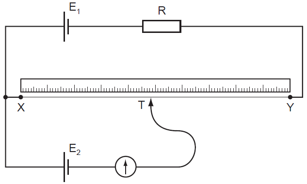
Potentiometer circuit physics diagram doubts help working circuits length shows cell
.
.


3 Pin Variable Resistor Diagram

DC Lab - Precision Potentiometer | DC Circuit Projects | Electronics

Linear Potentiometer

Potentiometer Schematic | Hackaday

potentiometer circuit diagram - Wiring Diagram and Schematics
