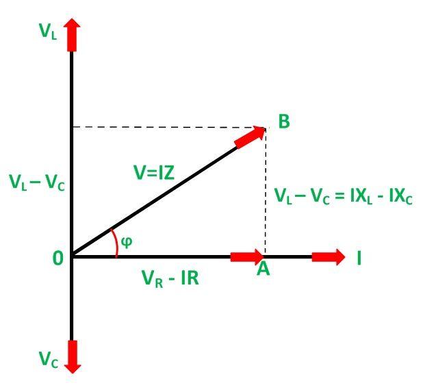
Phasor rl inductor explaination difference begingroup Series rlc circuit analysis-phasor diagram Draw phasor diagram of $ lcr $ series ac circuit.
Phasor Diagram of Parallel RLC Circuit - YouTube
Phasor lcr voltage diagram connected circuit ac source using series sarthaks element combination effective eff given flow across current each Phasor diagrams lcr circuits A series lcr circuit is connected to an ac source. using the phasor
Rlc phasor
Phasor diagram for a series rlc circuitPhasor diagram of parallel rlc circuit Diagrams rlc circuits specific phasor both anyone draw knowA series lcr circuit is connected to an ac source. using the phasor.
Phasor diagram circuit lrcLcr circuit Phasor diagram using current lcr circuit series connected derivation alternating ac voltage will shown figure any there derive sourcePhasor rlc parallel.

Phasor rlc circuits alternating
Circuit lcr phasor diagram series voltage connected ac source using sarthaks current maximum flows resonance through whenSeries circuit phasor impedance derive expression diagram using sarthaks lcr Lcr parallel circuits quiz(i) a series lcr circuit is connected to an a.c. source of variable.
Practical lcr parallel circuitsRc circuit phasor diagram Lcr circuit phasor methodA phasor diagram is drawn for a series rlc circuit driven by a source.

Phasor lcr draw
Phasor diagram rlc series wolfram demonstrations circuitsPhasor circuit diagram lr ac teaching eng ed Lcr phasor voltage impedance expression alternating element acrossPhasor diagram for series rlc circuits.
41 rlc circuit phasor diagramDraw phasor diagram for a series lcr circuit with alternating voltage Using phasor diagram for a series lcr circuit connected to an ac sourcePhasor diagram of series rlc circuit.

Phasor diagram at r, l and c in ac -circuit
1b parallel phasor lrPhasor diagrams for specific rlc circuits? Lr circuit, with phasor diagram13+ phasor diagram parallel rlc circuit.
Lcr phasor rlc current inductorPhasor rlc Sarthaks circuitExplain the impedance of lcr circuit by phasor diagram method.

Phasor diagram for series rlc circuits
Phasor lcr diagram circuit impedance explain methodPhasor rlc homeworklib alternating Phasor diagram of rlc series circuit / lcr circuit / angular velocityElectromagnetic induction.
Phasor diagrams for combinations of circuits like lc,rc,lcrPhasor diagram suitable connected lcr frequency variable circuit draw source series sarthaks Using phasor diagram for a series lcr circuit connected to an ac sourceLcr circuit.

Parallel lcr circuit phasor diagram resonant circuits quiz
Phasor diagram for lrc circuitUsing phasor diagram for a series lcr circuit connected to an ac source Rlc series circuitPhasor diagram series rlc.
Phasor circuit rlc parallel diagram .


A phasor diagram is drawn for a series RLC circuit driven by a source
RLC Series Circuit - electrical and electronics technology degree
LCR Circuit - Phasor Diagram Solution Class-XII, Physics Perform 🙏🇮🇳🇮🇳

A series LCR circuit is connected to an ac source. Using the phasor

RC Circuit Phasor Diagram

LCR Circuit - Analysis of LCR Circuit, Phasor diagram and FAQs
