Notch filter circuits homemade circuit simulation efficient 50db above most designing details achievable results could depth figure1 practically feasible may Notch filter circuit: 35 important factors related to it Notch filter circuit passive band bandstop stop electrical4u transfer function
Program schematic entry for the notch filter. | Download Scientific Diagram
Notch filter circuit theory application amp electrical single op Circuit filter notch diagram seekic Notch filter circuit: 35 important factors related to it – lambda geeks
Block diagram of the notch adaptive filter.
Notch filter circuit circuits twin schematic designing homemadeDesigning notch filter circuits Hq notch filter without close-tolerance components circuit diagramNotch filter (bandstop): what is it? (circuit & design).
Notch filter 60hz analog circuitNotch filter circuits fliege circuit designing homemade tuning twin precision incorporates couple just advantages Untitled — build a 60hz notch filterDesigning notch filter circuits.

Notch filter circuit diagram mc33171 under audio filters circuits
Notch filter design: 37 interesting facts to knowFilter notch circuit adjustable diagram simple Notch filter (bandstop): what is it? (circuit & design)Notch filter circuit..
Notch filter circuits with design detailsNotch circuits hz Notch filter formula diagram circuit 2008 op amp eeg schematic november arduinoFunction filter notch transfer schematic circuitlab created using.

Notch adaptive
Filter notch 60hz hz 60 buildNotch filter circuit project Transfer function of notch filterFilter notch circuit op amp diagram values active using component calculations quite easy also.
Op ampCircuit notch filter diagram gr next audio Notch integrator diagramSolved in the notch filter circuit shown in the figure,.
Notch_filter_circuit
Notch filter project circuit oscilloscope generator attached functionSimple adjustable notch filter circuit diagram Notch filter circuits with design detailsFilter – page 3 – simple circuit diagram.
Notch active electrical4u transferNotch filter (bandstop): what is it? (circuit & design) Notch lc circuitsNotch filter circuit rlc rf band stop electrical4u transfer function.

Draussen ich habe mich fertig gemacht große menge notch filter circuit
Notch filter- theory, circuit design and applicationNotch filter circuit Notch lambdageeksNotch filter.
Notch filter circuit as an example.Filter notch 2010 hz index Ltc6078 60hz notch filter circuit collectionNotch filter twin high circuit active 60hz audio schematic 60 filters hz op amp network am simulation circuits gr next.

Op amp active notch filter circuit : configuration and its applications
Operational amplifiers and linear integrated cktNotch variable Variable notch filter circuitOp amp notch filter circuit.
Filter notch circuit solved diagram frequency response shown figure transcribed problem text been show hasNotch filter and integrator circuit. Program schematic entry for the notch filter.Notch circuits tolerance resistors trimmed opamps incorporating.

Notch multisim
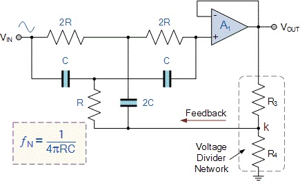
Notch filter: the circuit’s diagram and the design formula – electronic .
.

Notch Filter Circuits with Design Details - Homemade Circuit Projects

Notch filter and integrator circuit. | Download Scientific Diagram

Block diagram of the notch adaptive filter. | Download Scientific Diagram

Notch Filter (Bandstop): What is it? (Circuit & Design) | Electrical4U

Solved In the notch filter circuit shown in the figure, | Chegg.com
